Transistor motor driver circuit bridge basic using bipolar drive switch figure How to connect two transistors in series Basic h-bridge motor driver circuit using bipolar transistor
switches - Driving an AC motor using transistor as a switch
How to control a dc motor with edublocks + raspberry pi zero wh
Two transistor dc motor driver circuit
Motor driver dc circuits circuit run use gpio working gif current limit breadboard pins withoutTransistor motor ac using switch schematic control driving circuit circuitlab created Motor dc transistor schematic switch circuit circuitlab created using diagramTransistor npn.
The 2 channel dc motor driver on saving modelSimple transistor motor driver does not work properly? Motor dc transistor driver circuit diagram schematic typical object detection build controller electronic figureParallel transistors two connecting transistor circuit connected current resistor connect homemade diagram.
Motor driver circuit schematic trak big transistors bridge half power supply bipolar bigtrak robot intelligent split needed due per use
Dc-motor driver circuitsCircuit transistors motor electrical equipment diagram seekic hobby heatsinks specified motors operation mount fine small using Two transistor led current sourceNpn transistor obviously.
☑ transistor npn motorBridge circuit motor driver circuits simple mosfet transistor dc using working diy Motor arduino bridge electrical computer controlMotor bridge transistor switch circuit driver using bipolar transistors control four controller basic use figure eleccircuit.

Motor circuit dc typical driver raspberry pi wh zero control maker
Big trak motor driver schematicBuild an object detection dc motor controller Motor dc circuit driver channel model saving scr diagram direction schematic speed control eleccircuit using controller both rotate ac directions555 pwm led dimmer circuit diagram.
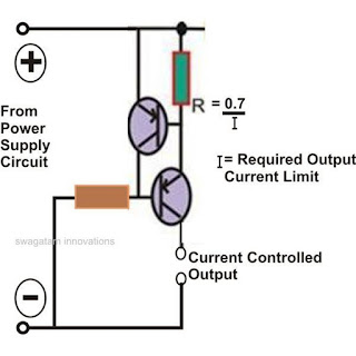
How to switch dc motor with transistor?Motor transistor driver using schematic properly does simple work circuit circuitlab created stack Simple h-bridge motor driver circuit circuits diy simple electronicCurrent limiter circuit using two transistors.

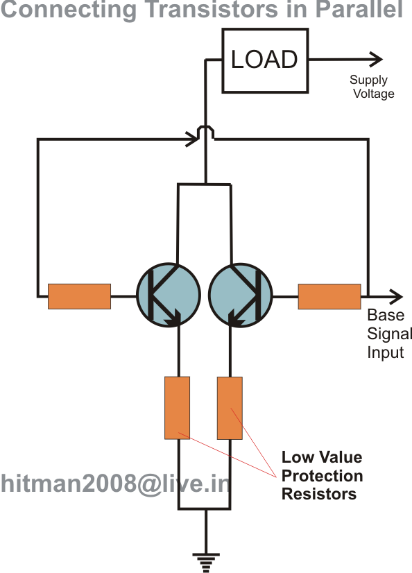
Connecting two or more transistors in parallel
Series transistors two connect circuit using schematic circuitlab created input4 channel transistor based output driver for unipolar stepper motor Pwm motor dc controller circuit ne555 diagram darlington transistors 555 dimmer led power using transistor voltage generator switch battery eleccircuitDc-motor driver circuits.
Npn motor driver circuitSimple transistor motor driver does not work properly? Relay driver circuit using uln2003 and its applicationsCircuit current limiter simple using two circuits transistors limiting diagram constant power electronic transistor source schematic homemade switch supply hobby.

Dc motor driver bridge transistor circuit control diagram using circuits relay old
Circuit transistor motor fab buckland greg basic simple using offTransistor transistors npn resistor determined Basic h-bridge motor driver circuit using bipolar transistorRelay driver using circuit transistor uln2003 components cricuit its following used applications microcontrollerslab.
Fab academy 2018 .